Trending Now: FEA, CFD & Artifical Intelligence Simulation and Design for Medical and Biomedical Applications 
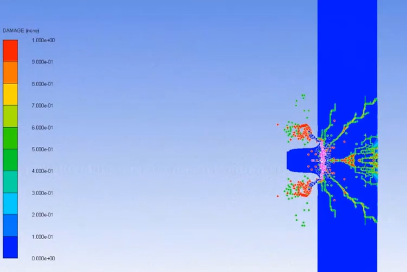
Blast, Explosion & Fire
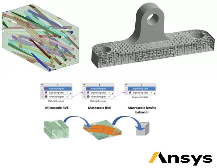
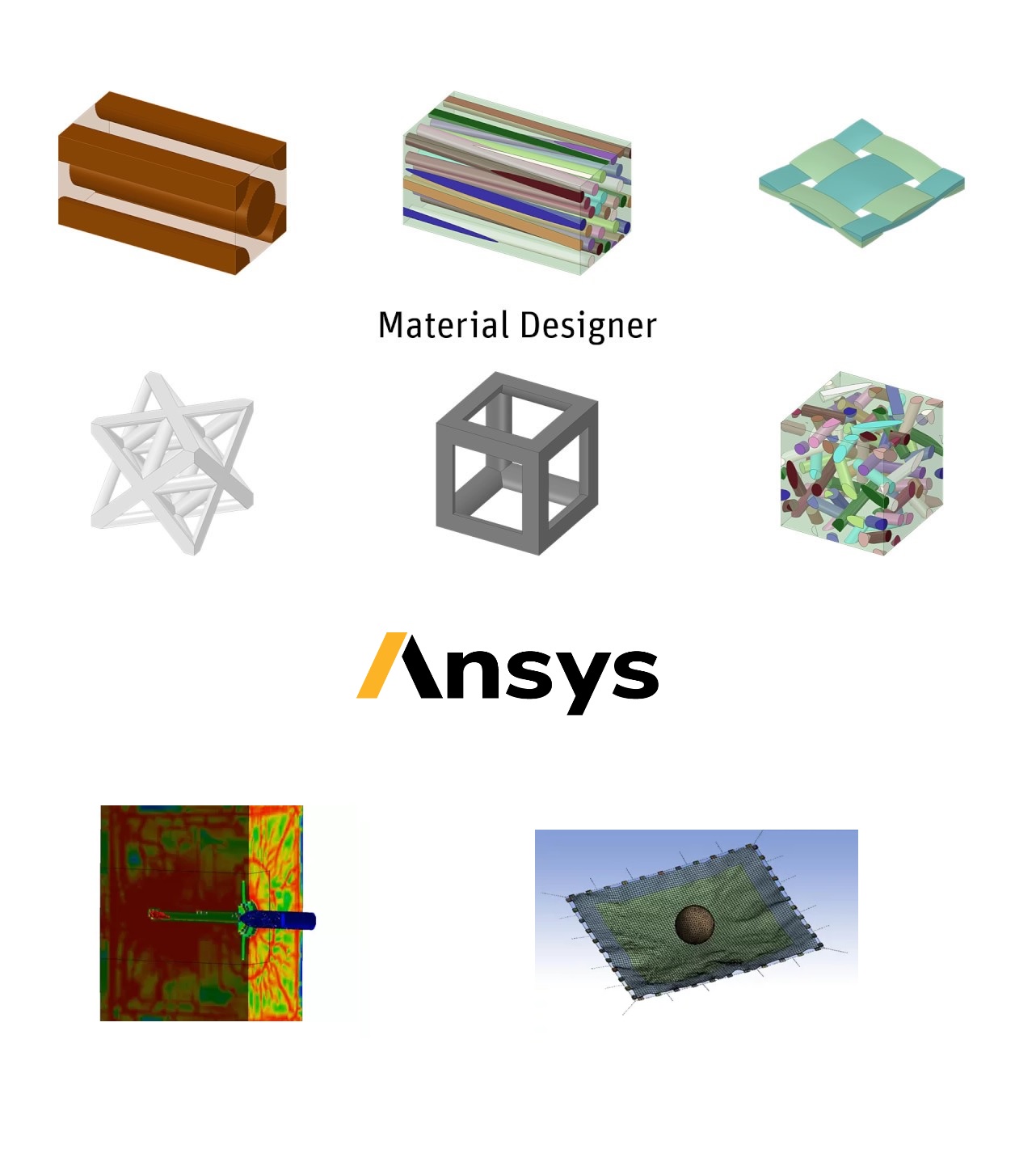
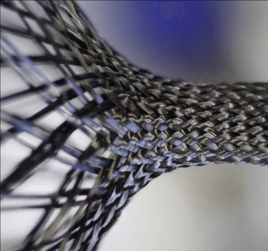
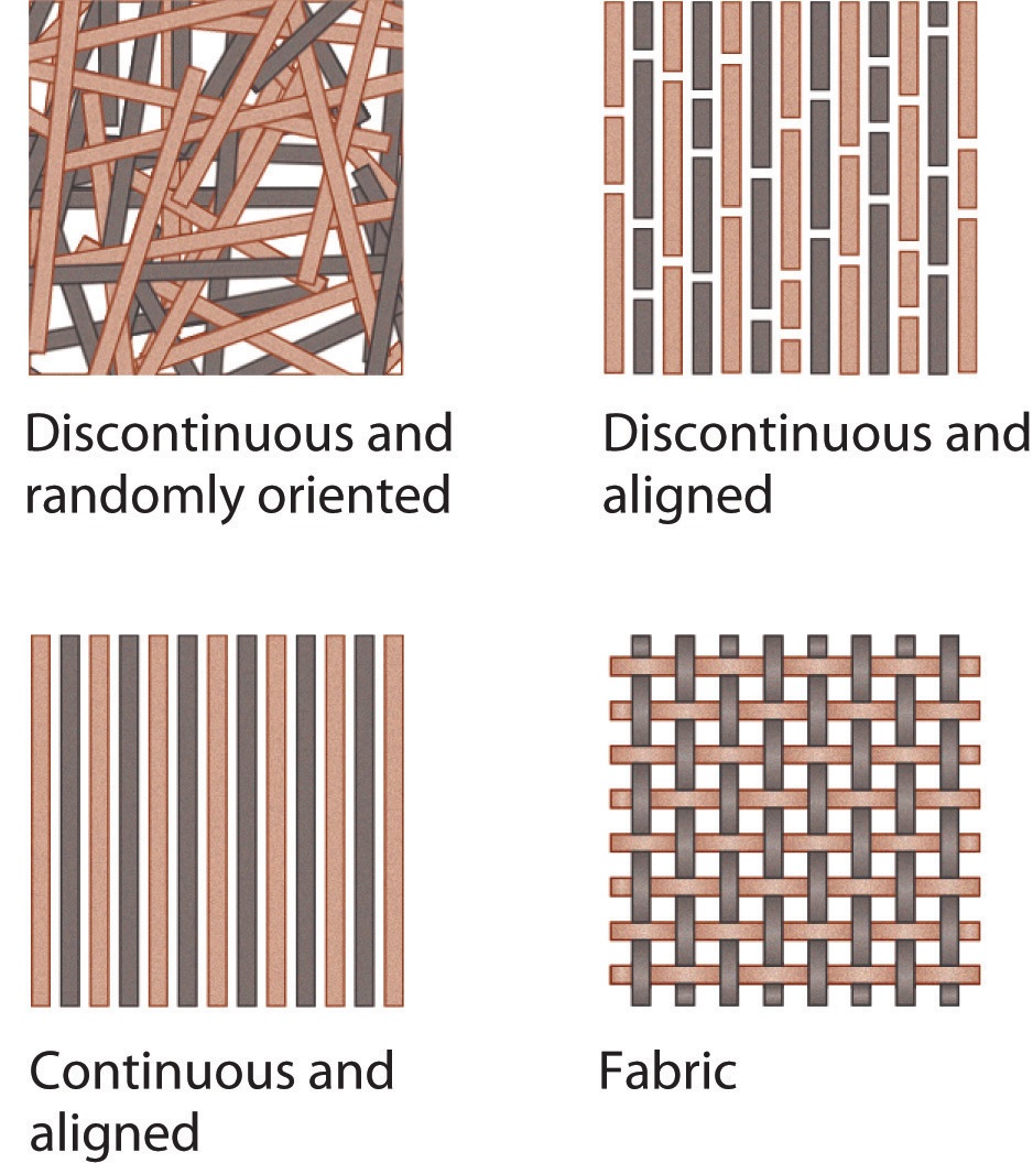
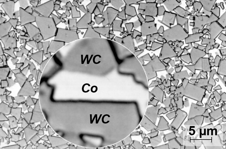
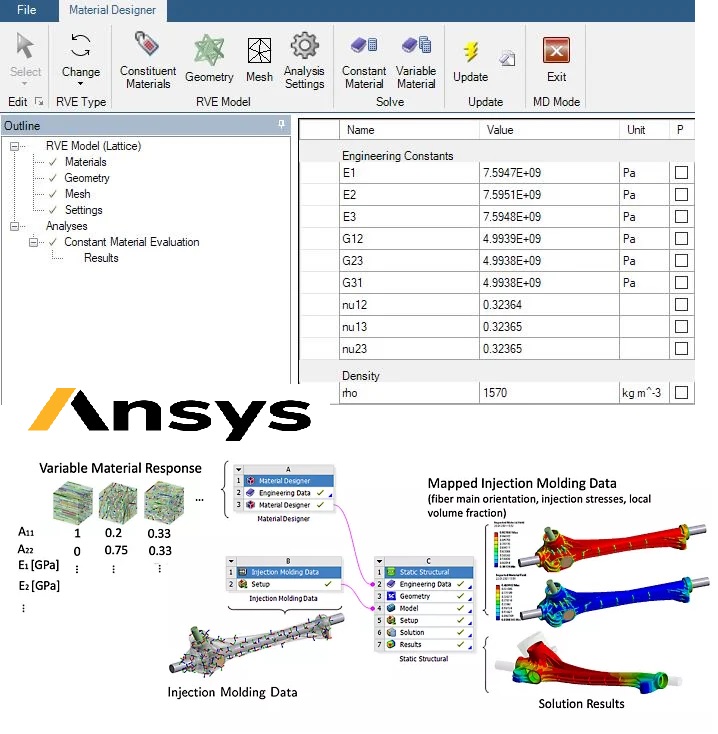
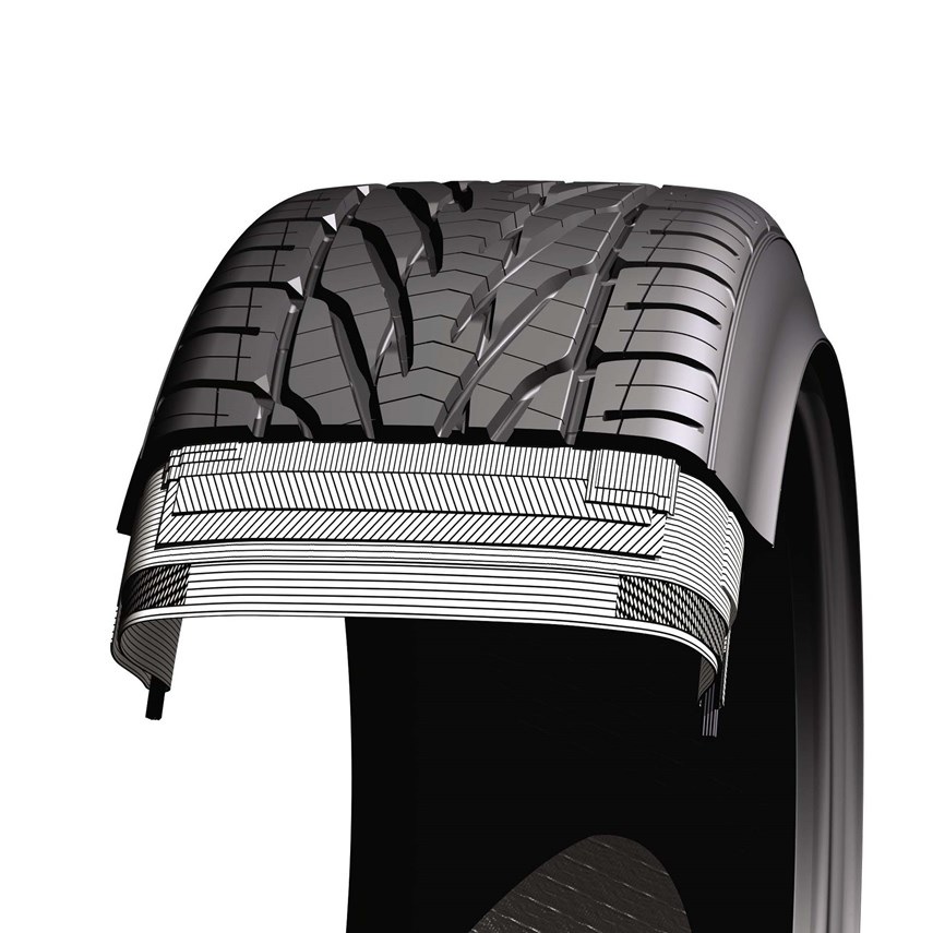
: air blast, Underwater explosion (UNDEX) and Fragmentation. VTOL, e-VTOL and UAM - Urban Air Mobility.
IMG-LOGO
Modern Engineering Tabs Interface

Composite Materials

Composite Materials Artificial Intelligence Analysis FEA|CFD & AI Integration

Composite material modeling Consultant, Training and Simulation services of Simulation Dynamics cover wide range of industry using advanced FEA Technology for design, ultimate failure, fatigue, fracture, impact, crash, environmental degradation, acoustics and multiphysics simulations with sophisticated FEA solvers such as Abaqus, Ansys, LS-DYNA, RADIOSS and COMSOL.

Contact US and Discover Solutions
Composite Materials, Integrated FEA|CFD with Artificial Intelligence

Composite modeling approach in numerical computation

Cohesive zone models (CZMs): CZMs are commonly used to model the initiation and propagation of cracks and delamination in composite materials. These models simulate the behavior of the material at the crack tip by representing the material as a series of cohesive elements that connect the two sides of the crack. The CZM parameters are usually calibrated from experimental tests or from higher fidelity simulations, and can be used to predict the critical load required to initiate and propagate cracks and delamination in composite structures.

Damage models: Damage models are commonly used to simulate the progressive degradation of the composite material due to fatigue loading or other internal or external factors. These models simulate the accumulation of damage in the material, such as matrix cracking or fiber breakage, by using damage evolution laws.

Continuum damage mechanics models (CDMs): CDMs simulate the degradation of the material by considering the evolution of damage at the continuum scale. These models are typically used to simulate the behavior of composite materials under various loading conditions, including static and dynamic loading. The damage parameters are usually calibrated from experimental tests or from higher fidelity simulations.

Failure criteria models: Failure criteria are commonly used to predict the onset of failure in composite materials. These models are based on stress or strain-based criteria and are calibrated from experimental tests or from higher fidelity simulations.

Micromechanical models: Micromechanical models simulate the behavior of composite materials at the microscale, taking into account the interactions between the constituent materials, such as fibers and matrix. These models are typically used to predict the mechanical properties of the composite material, such as stiffness and strength, and to optimize the composite material design.

XFEM is a technique that allows for the simulation of crack propagation without the need for remeshing the material. This is particularly useful for simulating the behavior of composites, which have a complex microstructure that can be difficult to mesh. XFEM has been used to simulate the fracture behavior of composites under different loading conditions, such as tension and bending.

Engineering Reliability, One Simulation at a Time.

Finite Element Anlaysis(FEA) and Computational Fluid Dynamics(CFD) ensures your designs are built to last. From automotive to aerospace, analyze structural integrity with precision. Trust in reliable solutions. Whether predicting pressure drop, thermal shock, stress, strain, or deformation, FEA & CFD delivers the insights you need to innovate with confidence. Build products that perform under pressure.

Simulation Dynamics
Composite modeling approach in numerical computation, Ansys, Simulia, Siemens, Integrated FEA|CFD with Artificial Intelligence
Advanced Engineering Solutions

High-rate loading conditions: Impact, Crash, Blast and Explosion

Composite materials can exhibit complex behavior under high-rate loading conditions, including fracture, damage, and delamination. High-rate loading conditions refer to situations where the loading rate is very rapid, such as in impact or blast loading scenarios.

In these situations, the material experiences significant dynamic effects that can cause different types of damage, such as matrix cracking, fiber breakage, and delamination. The dynamic effects can also cause the material to behave differently than under static loading conditions, such as increased stiffness, strength, and ductility.

To accurately model the behavior of composite materials under high-rate loading conditions, sophisticated material models and simulation techniques are required. For example, explicit dynamic FEA solvers such as LS-DYNA and Abaqus/Explicit are often used to simulate the transient response of the material under high-rate loading conditions. Material models such as CZMs, damage models, and CDMs are used to capture the different types of damage that can occur in composite materials under these conditions. These models are typically calibrated using experimental data from high-rate loading tests.

Additionally, it is important to consider the effects of temperature rise and the time-temperature dependence of the material response under high-rate loading conditions. The high-strain rates and rapid energy dissipation can lead to significant temperature rise within the material, which can affect its mechanical properties and behavior. Therefore, it is necessary to incorporate thermal-mechanical coupling effects in the material models used for high-rate simulations.

Moreover, to capture the complex behavior of composite materials under high-rate loading, it is also important to consider the microstructure and fiber/matrix interactions in the material. Micromechanical models, such as the multi-scale progressive failure analysis (MS-PFA) approach, can be used to simulate the microscale behavior of the material, and provide insights into the damage mechanisms and failure modes under high-rate loading.

Artificial Intelligence & Machine Learning Powers the Future of Simulation.

Transform your simulations with AI-driven insights. Automate workflows, reduce time-to-market, and unlock new possibilities. Embrace the future of engineering. From CFD to FEA, AI enhances every aspect of simulation, delivering faster, more accurate results. Experience the next generation of intelligent engineering solutions.

Simulation Dynamics
High-rate loading conditions: Impact, Crash, Blast and Explosion, Ansys, Simulia, Siemens, Integrated FEA|CFD with Artificial Intelligence
Advanced Engineering Solutions

Braided Composites

Braided composites are a type of composite material that is made by braiding continuous fibers around a mandrel to create a preform, which is then impregnated with a resin matrix to create a final composite part. This process is different from other composite manufacturing processes like hand layup or filament winding, which involve cutting and placing pre-cut fibers onto a mold.

The main advantage of braided composites is their ability to create more complex parts with higher fiber volume fractions and better mechanical properties. This is because the braiding process allows for more precise fiber placement and tighter weaving of the fibers, which results in a more uniform and stronger material.

However, the downside of the braiding process is that it requires specialized equipment and tooling, which can be expensive and time-consuming to set up. Additionally, the process is limited to convex shapes and hollow profiles, which means that it may not be suitable for all types of parts.

AI Transforms Multiphysics Simulation.

Harness Artificial Intelligence & Machine Learning to solve complex multiphysics problems faster and more accurately. Optimize performance across fluid-structure interaction, thermal-electrical coupling, and more. Drive innovation with intelligent simulation.

Simulation Dynamics
Braided Composites, Ansys, Simulia, Siemens, Integrated FEA|CFD with Artificial Intelligence
Advanced Engineering Solutions

Discontinuous Fiber Composites

Discontinuous fiber composites (DFC) are a type of composite material that are made by compressing pre-impregnated fiber chips, or prepreg chips, which consist of unidirectional fibers and a matrix material. These chips are typically arranged in a specific orientation and then compressed under high pressure and temperature to form the final composite part.

One potential issue with the manufacturing process for DFCs is the occurrence of cracks between the chips. This can happen when the curing cycle is not well monitored, as thermal stresses can build up between adjacent chips when they are heated to the curing temperature. These thermal stresses can cause the matrix material to crack or fracture, resulting in gaps or voids between the chips in the final composite part.

To prevent this issue, it is important to carefully monitor and control the curing cycle, including the temperature and pressure applied during the compression molding process. Additionally, the use of thermoplastic matrices instead of thermoset matrices may also help to reduce the occurrence of cracks, as thermoplastics typically have better toughness and can better handle the thermal stresses generated during the curing process.

Generative Design + CFD: Topology-Optimized Fluid Dynamics

Combine genetic algorithms with RANS/LES simulations to auto-generate weight-optimized turbomachinery blades, heat sinks, and microfluidic devices.

Simulation Dynamics
Discontinuous Fiber Composites, Ansys, Simulia, Siemens, Integrated FEA|CFD with Artificial Intelligence
Advanced Engineering Solutions

Hard Metal

Hard metals, also known as cemented carbides, are composite materials that are made up of a metal matrix and a hard ceramic phase. The metal matrix typically consists of cobalt, nickel, or iron, while the hard ceramic phase is composed of tungsten carbide, titanium carbide, or tantalum carbide.

The microstructure of hard metals is critical to their mechanical properties, as it determines the distribution and size of the hard ceramic inclusions within the metal matrix. By varying the content and microstructure of the hard inclusion phase, it is possible to tune the material properties of the hard metal, including its hardness, strength, and wear resistance.

One key challenge in optimizing the microstructure of hard metals is managing the stresses that are generated during the manufacturing process. These stresses can lead to cracking or deformation of the material, which can affect its mechanical properties and overall performance. To mitigate these stresses, it is important to carefully control the manufacturing process, including the composition of the metal matrix and the processing conditions, such as temperature, pressure, and cooling rate.

Cognitive FEA: Machine Learning-Predictive Structural Integrity

Deploy graph neural networks (GNNs) to forecast nonlinear material deformation, crack propagation, and fatigue failure. Train AI on legacy FEA datasets for ISO-certified validation of aerospace composites, additive manufacturing defects, and seismic-resistant infrastructure.

Simulation Dynamics
Hard Metal, Ansys, Simulia, Siemens, Integrated FEA|CFD with Artificial Intelligence
Advanced Engineering Solutions

Plastic materials

Designing plastic materials reinforced with glass and/or carbon fibers is a complex process that requires consideration of many factors, including the properties of the base plastic material, the type and length of fiber reinforcement, and the manufacturing process used to produce the final part. Advanced CAE software can be used to investigate the performance of these materials, including modal analysis, creep, stiffness, crash, and durability/fatigue.

One of the most important challenges in using CAE software for the design of plastic materials is taking into account the effect of the manufacturing process on the performance of the final part.

To address this challenge, it is important to use FEA solvers that is specifically designed to model the manufacturing process and its effects on the material properties. This may include using specialized software modules that can simulate the molding process, such as filling analysis, cooling analysis, and warpage analysis. Additionally, it may be necessary to perform experimental testing on samples produced using the same manufacturing process to validate the simulation results and ensure that the final part will meet the desired performance specifications.

Our cutting-edge Artificial Intelligence & Machine Learning integrated development solutions combine technical excellence with business insight to deliver exceptional digital experiences.

We leverage modern frameworks with CFD & FEA solvers and cloud infrastructure to build applications that scale seamlessly with your industrial needs.

Simulation Dynamics
Plastic materials, Ansys, Simulia, Siemens, Integrated FEA|CFD with Artificial Intelligence
Advanced Engineering Solutions

Rubber Matrix Composite

Rubber-based components, such as tires, anti-vibration systems, seals, and hoses, rely on the properties of the rubber matrix to perform their intended function. However, these properties can be significantly enhanced by embedding inclusions, such as carbon black, mica particles, or steel fibers, into the rubber matrix.

The inclusion of carbon black or mica particles into the rubber matrix is a common way to tune the material properties of rubber-based components. Carbon black, for example, can improve the wear resistance, tensile strength, and tear resistance of the rubber matrix, while mica particles can enhance the thermal conductivity and electrical insulation properties.

In addition to these microscopic inclusions, more complex systems like tires often contain macroscopic inclusions, such as steel fibers. These fibers are embedded into the rubber matrix in a sophisticated weave, which helps to control the footprint of the tire and enhance its performance. For example, steel fibers can improve the tire's resistance to punctures, increase its grip on wet or slippery surfaces, and enhance its overall durability and stability.

Multiphysics AI: Simulate Fluids, Structures, & Electromagnetics

Model EV motor cooling, MEMS sensors, and satellite thermal-vibration coupling. Use pytorch/TensorFlow-integrated solvers to automate boundary conditions and predict multiphysics failures in mission-critical systems.

Simulation Dynamics
Rubber Matrix Composite, Ansys, Simulia, Siemens, Integrated FEA|CFD with Artificial Intelligence
Advanced Engineering Solutions

Unidirectional composites (UD)

Unidirectional composites (UD) are a type of composite material that consist of fibers arranged in a single direction within a matrix material. These composites offer a wide range of options for tuning the material properties to meet specific performance requirements. They are commonly reinforced with different types of fibers, such as glass, carbon, or aramid, and can be made using both thermoset and thermoplastic matrices.

The fibers used in UD composites are typically straight and non-crimped, which allows for maximum efficiency in transferring load along the length of the fiber. The fibers are arranged in specific stacking sequences, with varying fiber volume fraction, ply thickness, and orientation, to achieve the highest possible in-plane laminate properties in the final composite component construction.

By varying the stacking sequence and fiber orientation, UD composites can be tailored to achieve specific mechanical properties, such as stiffness, strength, and toughness, in specific directions. This makes them ideal for applications that require high performance in certain directions, such as aerospace, automotive, and sports equipment.

AI-Driven Simulations for Smarter Engineering.

Leverage Artificial Intelligence to optimize CFD, FEA, and multiphysics simulations. Automate workflows, reduce errors, and accelerate innovation. Transform your engineering processes with AI-powered insights.

Simulation Dynamics
Unidirectional composites (UD), Ansys, Simulia, Siemens, Integrated FEA|CFD with Artificial Intelligence
Advanced Engineering Solutions

Woven fabric composites

Advanced FEA tools are essential for material investigations and are used to simulate the behavior of materials under various loading conditions. An advanced woven model is a type of finite element model that is capable of accurately representing the underlying weave pattern and yarn structure of composite materials.

By taking into account the underlying weave pattern and yarn structure, advanced woven models can accurately simulate the mechanical behavior of composite materials under different loading conditions, including tension, compression, bending, and shear. This allows for the prediction of material properties such as stiffness, strength, and fracture toughness, which are critical for the design and optimization of composite components.

In addition, advanced woven models can also consider weave patterns in which the warp yarns go across multiple layers of weft yarns. These types of weave patterns improve the interlaminar toughness and impact resistance of the material, making it more resistant to damage and failure.

Structural analyses based on local warp/weft information from draping simulations can also be set up using advanced FEA tools. This allows for the accurate prediction of the mechanical behavior of composite materials during the manufacturing process, which is critical for ensuring the quality and performance of the final product.

Solve Complex Problems with Multiphysics Simulation.

Combine forces, heat, fluids, and more in a single multiphysics simulation platform. Drive innovation across aerospace, automotive, and energy sectors. Experience the power of integrated engineering solutions.

Simulation Dynamics
Woven fabric composites, Ansys, Simulia, Siemens, Integrated FEA|CFD with Artificial Intelligence
Advanced Engineering Solutions